Whether you’re tracking, mixing or mastering, the Rupert Neve 543 delivers unobtrusive, musical dynamic control and high-ratio limiting with massive flexibility, transparency and precision.
The Rupert Neve 543 Compressor is available to audition in our showrooms.
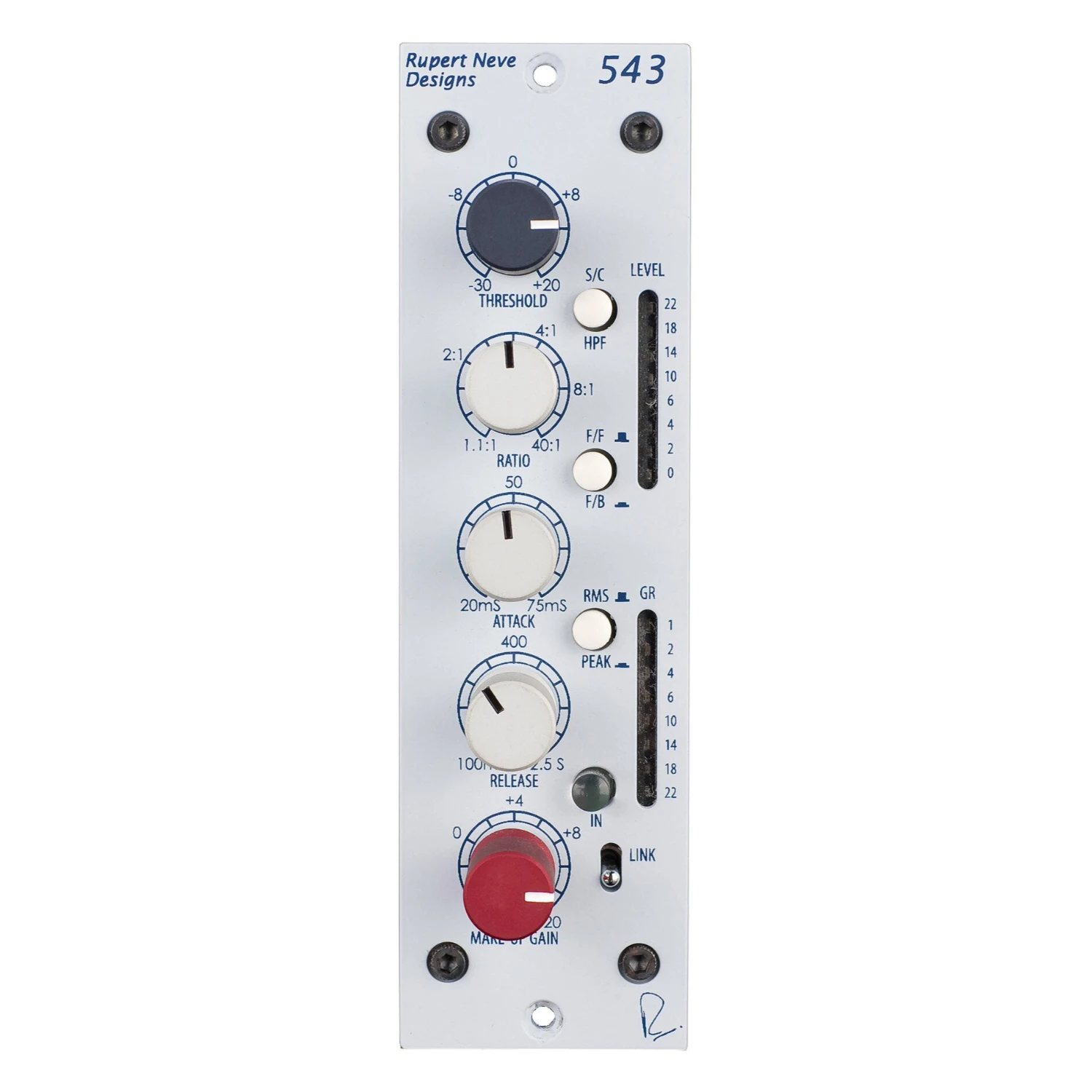
The 543 features a fully controllable compressor-limiter with feed-forward / feedback modes, Peak / RMS detection and a built-in side chain high pass filter. With an unrivaled heritage and a tremendous feature set, the 543 provides an astonishing degree of flexibility and precision.
What is VCA compression?
Every compressor has a gain control element in its circuit, and this is generally what determines the “sound” of the compressor. Some compressors use tubes, some use FETs, some use light-dependent resistors, some use a diode bridge – but in the Rupert Neve 543, a VCA (Voltage Controlled Amplifier / Attenuator) is used to control the signal’s gain.
In contrast to a diode bridge design like our 535 compressor, which adds a thick, very colorful tonality to the source, the 543 makes use of a very accurate, low noise, low distortion VCA. This provides an immense amount of dynamic control and subtle warmth, without necessarily leaving a heavy sonic imprint on your tracks or mixes.
Feed-Forward or Feed-Back?
This switch changes the point in the signal path where the VCA control voltage is picked off: either before the VCA (feed-forward) or after the VCA (feed-back).
In most of Mr. Neve’s earliest designs, feed-back detection was intrinsic to the musical dynamic response. However, the very nature of a feedback compressor limits the attack time of the compression circuit, as the control voltage has already passed through the VCA itself. To offer faster, more technically accurate response times, feed-forward detection was also implemented in the 543: with the FF / FB switch, both classic and modern VCA responses are available.
RMS or Peak?
Another highly useful features of the Rupert Neve 543 is the Peak / RMS mode, which allows the VCA to respond to both RMS (Root Mean Square) and peak levels. RMS circuits are considered to better mimic the way the ears perceive apparent loudness, while peak circuits tend to directly respond to the waveform voltage, which may be more of a concern for prevention of clipping and maximizing levels.
In the case of this particular circuit, peak mode actually uses a combination of both methods to get the best of both worlds, and avoids the drawbacks of each method on its own.
Threshold
Sets level where the compressor may begin to react from -30 dB to +20 dB. Minimal or no compression is with this control fully clockwise and it gets more sensitive and tends to cause more gain reduction as the knob is rotated counter-clockwise (which may be counter-intuitive to some).
Ratio
Sets the “slope” of the compression from 1.1:1 (minimal) to 40:1 (Limit) . For example, if set for 3:1 and the input signal rises by 3dB, the output signal will only rise by 1dB. In general, low ratios can not damage the music as much as high ratios but high ratios may be more useful to minimize clipping and OL lights in the recorder.
Comp In
Engages the compressor section of the unit.
F/F + F/B
These are two very different compressor modes, FEED FORWARD and FEED BACK. The F/B mode (button in) tends to sound smoother and often more natural and tends to be quicker to set up. The F/F mode can be more useful for shaping the envelope of the sound and introducing more bounce and pumping in time with the song, when that is the goal.
Gain
Continuously variable from -6 dB to +20 dB.
Attack
This sets how quickly the compressor reacts and starts attenuating. Continuously variable from 20mS to 75mS.
Release
This sets how fast the compressor returns back to zero after attenuating. Typically engineers use slower release times when the intention is to minimize any obvious compressor action or gains changing. Continuously variable from 100mS to 2.5 Seconds.
RMS/PEAK
This changes the compressor from essentially responding to the RMS level of the audio to also responding to the PEAK level. RMS (root mean squared) circuits are considered to better mimic the way the ears perceive apparent loudness, while Peak circuits tend to directly respond to the waveform voltage which may be more of a concern for prevention of clipping and maximizing levels.
Sidechain HPF
This routes a high pass filter set to 250 Hz into the circuit that the compressor uses to determine level. Note that the rest of the circuit and output will not have those lows filtered out – this only determines the portion of the signal that is affected by the compressor. This is very useful when you want your low frequency content to come through unaffected while still compressing the mids and highs.
Link
When link buss is provided by the 500 series rack, this can be used to link the reduction of two 543 units together.
GAIN RANGE
Continuously variable from -6 dB to +20 dB
THRESHOLD RANGE
Continuously variable from -30 dB to +20 dB
RATIO RANGE
Continuously variable from 1.1:1 to Limit (40:1)
ATTACK RANGE
Continuously variable from 20mS to 75mS
RELEASE RANGE
Continuously variable from 100mS to 2.5 Seconds
TOTAL HARMONIC DISTORTION AND NOISE
@ 1 kHz, 0 dBu output level, no load.
Main Output, compressor bypassed: Better than 0.002%
@ 20 dBu better than 0.0015%
Main output, compressor engaged: Better than 0.075%
NOISE
Measured at Main Output, un-weighted, 22 Hz – 22 kHz, Terminated 50 Ohm.
With Gain at Unity, Compressor disengaged: Better than -98 dBu
With Gain at Unity, Compressor engaged: Better than -93 dBu
FREQUENCY RESPONSE
Main Output, Unity Gain: @ 150 kHz -3 dB
METERS
Monitors INPUT LEVEL and GAIN REDUCTION
LINE INPUT IMPEDANCE
10,000 Ohms
MAXIMUM OUTPUT LEVEL
21 dBu from 20 Hz to 40 kHz
POWER REQUIREMENTS
500 series rack with 110-125 mA @ +/- 16V
Download the User Manual in PDF format.
$1,786 Inc GST
‘Ordio Productions’ and the Ordio Productions Logo are owned exclusively by Ordio Productions
If you have any questions, please contact us
All content is the copyright of Ordio Productions and cannot be used without written permission